


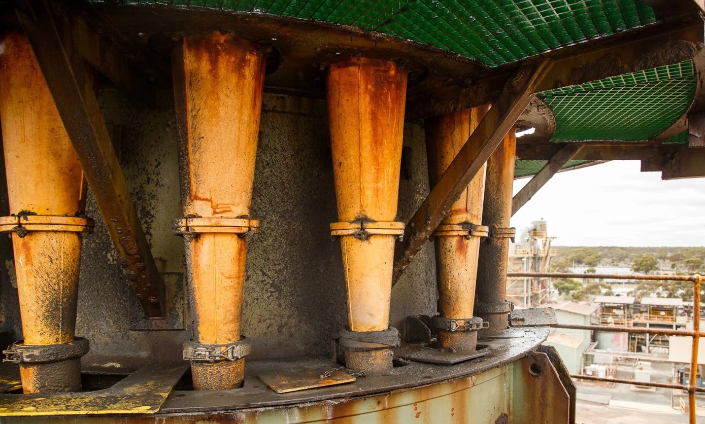
Application
Roping refers to the formation of a rope-like structure within the cyclone, disrupting the normal flow patterns. This phenomenon reduces the separation efficiency of the cyclone, leading to a lower yield of valuable minerals and increased energy consumption. Roping can occur unexpectedly due to various factors such as changes in feed composition, flow rates, and particle size distribution, and it is challenging to predict when roping will happen using traditional control systems. When roping occurs, it often results in production losses, as the cyclone cannot effectively separate the desired minerals from the waste material, leading to financial losses for mining operations. Roping can also cause excessive wear and tear on cyclone components, increasing maintenance costs and downtime for repairs and replacements.
Cyclones are very sensitive to process changes, and they are hard to control. Under normal operating conditions the cyclone underflow discharge angle is in a splash state. As the pressure increases in the cyclone, the separation efficiency increases by increasing the density of the underflow, improving the bypass of fines. This is the ideal operating mode, also known as semi-roping.
Further increasing the pressure, larger particles will increasingly report to the overflow, reducing the flow of the underflow and collapsing the air core and the vortex in the final stage, which is known as roping.
The underflow discharge angle provides invaluable information about the operation of the cyclone. The closed-loop control of the discharge angle would allow maximum throughput and separation efficiency.
Solution: Computer Vision-based Roping Detection
Detecting roping in cyclones offers the opportunity to improve separation efficiency. By identifying and mitigating roping events in real time, mining operations can maintain consistent production rates and maximise mineral recovery. Roping detection can lead to energy savings by preventing the need for excessive adjustments and interventions in cyclone operation when roping occurs, contributing to reduced operational costs. The detection of roping relies on the analysis of various data sources, including flow rates, pressure, density, and vibration. Implementing AI and machine learning models for roping detection provides valuable insights into cyclone behaviour, which can be used for process optimisation. Improving cyclone efficiency through roping detection can enhance safety by reducing the need for manual interventions and adjustments, which can be risky in mining environments. Roping detection can also help in predictive maintenance planning: by monitoring cyclone performance and identifying early signs of roping, maintenance teams can schedule maintenance activities more efficiently, minimising downtime.
Technology
Roping events and liner wear can influence some of the same underflow signals, so they should be treated as related but separate conditions. Cyclone Apex Liner Wear Estimation uses persistent, pressure- and feed-conditioned drift rather than a single roping event to support maintenance planning.
Designing a Convolutional Neural Network (CNN) for binary classification to recognise roping events involves several steps. This process includes data collection and preparation, architecture design, training, and deployment. Here’s a detailed breakdown.
1. Data Collection and Preparation
- Collecting images: capture a large number of images showing both normal operation and roping events. Ensure varied lighting and environmental conditions are represented.
- Labelling: annotate these images, labelling them as ‘Normal’ or ‘Roping’. This step is critical for supervised learning.
- Preprocessing: standardise the images (resize, normalise pixel values, etc.). Consider augmenting the data set with techniques like rotation, flipping, or adding noise to improve the model’s robustness.
2. Architecture Design
- Input layer: design the input layer to accept the standardised image size.
- Convolutional layers: these layers extract features from the images. Use multiple convolutional layers, with each layer detecting more complex features. Include activation functions like ReLU to introduce non-linearity.
- Pooling layers: following convolutional layers with pooling layers (like max pooling) reduces the spatial size of the representation, lowering the number of parameters and computation in the network.
- Fully connected layers: after several convolutional and pooling layers, add one or more fully connected layers for classification. These layers use the features extracted by previous layers to determine the image’s class.
- Output layer: since it is a binary classification (Normal or Roping), the output layer should have a single neuron with a sigmoid activation function, which outputs a value between 0 and 1, indicating the probability of a roping event.
3. Training the CNN
- Loss function: use a binary cross-entropy loss function, which is suitable for binary classification problems.
- Optimiser: choose an optimiser like Adam or SGD for adjusting weights during training.
- Validation set: split the data into training, validation, and test sets. The validation set helps in tuning the hyperparameters and avoiding overfitting.
- Training: train the network using the training dataset. Monitor the performance on the validation set to adjust parameters like learning rate, number of epochs, or layers.
4. Evaluation and Tuning
- Performance metrics: evaluate the model using metrics like accuracy, precision, recall, and F1 score.
- Tuning: based on the evaluation, tune the model by adjusting its architecture, hyperparameters, or training data.
- Overfitting check: ensure that the model is not overfitting the training data. Techniques like dropout, regularisation, or augmenting more data can help.
5. Deployment
- Integration: integrate the trained model into the control system for real-time analysis.
- Monitoring and updating: continuously monitor the model’s performance in real-world conditions and update or retrain as necessary.
Challenges and Considerations
- Varying conditions: the model should be robust to variations in lighting, material properties, and operating conditions.
- Real-time processing: the CNN must process images quickly enough to allow real-time detection and response to roping events.
- Resource constraints: consider the computational resources available, as more complex models require more processing power.
Operating mode
Configured per site
The approved operating mode depends on the site, available data, validation results and safety case. A capability may begin as monitoring or advice, then progress to supervised or closed-loop control. Existing PLC, DCS and safety interlocks remain the final authority on what equipment can do.
Read about deployment and assurance